

कम वायु प्रवाह से अक्सर छोटे कणों को पकड़ने में सुधार की उम्मीद की जाती है क्योंकि वे फिल्टर माध्यम में लंबे समय तक रहते हैं और ब्राउनियन प्रसार अधिक प्रभावी हो जाता है. फिर भी प्रयोगशाला या उत्पादन परीक्षण कभी-कभी कम वायु प्रवाह बिंदु पर कम दक्षता की रिपोर्ट कर सकता है.
उस परिणाम को तुरंत एक विशेष निस्पंदन तंत्र के रूप में नहीं समझाया जाना चाहिए. कई मामलों में, पहला सवाल यह नहीं है कि "फ़िल्टर ख़राब क्यों हो गया।"?” लेकिन “क्या निम्न-प्रवाह परिणाम वैध और तुलनीय स्थितियों के तहत मापा जा रहा है?”
यह आलेख जांच का एक व्यावहारिक क्रम प्रस्तुत करता है.
तुलना की जा रही मात्रा से प्रारंभ करें
तुलना की जा रही मात्रा से प्रारंभ करें
निस्पंदन दक्षता एक एकल सामग्री स्थिरांक नहीं है. यह कई परीक्षण स्थितियों पर निर्भर करता है, शामिल:
- कण आकार या कण-आकार वितरण;
- मध्यम वेग फ़िल्टर करें और फेस वेग फ़िल्टर करें;
- एरोसोल सामग्री और चार्ज स्थिति;
- फ़िल्टर कंडीशनिंग और इलेक्ट्रोस्टैटिक स्थिति;
- तापमान और सापेक्ष आर्द्रता;
- अपस्ट्रीम एकाग्रता और नमूनाकरण अवधि; और
- फ़िल्टर और सीलिंग प्रणाली की स्थिति.
तुलना तभी सार्थक है जब इन चरों को नियंत्रित किया जाए. फ़िल्टर क्षेत्र को जाने बिना "500 m³/h दक्षता" और "1,000 m³/h दक्षता" की सही व्याख्या नहीं की जा सकती, कण चैनल की तुलना की जा रही है, और परीक्षण विधि.
निस्पंदन सिद्धांत वास्तव में क्या भविष्यवाणी करता है
निस्पंदन सिद्धांत वास्तव में क्या भविष्यवाणी करता है
यांत्रिक रेशेदार निस्पंदन मुख्य रूप से प्रसार द्वारा नियंत्रित होता है, अवरोधन, और जड़त्वीय प्रभाव.
- बहुत छोटे कणों के लिए प्रसार सबसे महत्वपूर्ण है. कम वेग आम तौर पर इन कणों को स्ट्रीमलाइन से दूर जाने और फाइबर से संपर्क करने के लिए अधिक समय देता है.
- जैसे-जैसे कण का आकार बढ़ता है, अवरोधन अधिक महत्वपूर्ण हो जाता है और स्ट्रीमलाइन का अनुसरण करने वाला एक कण फाइबर के एक कण त्रिज्या के भीतर से गुजरता है.
- बड़े कणों और उच्च वेगों के लिए जड़त्वीय प्रभाव अधिक महत्वपूर्ण हो जाता है क्योंकि कण फाइबर के चारों ओर हवा का पालन करने में कम सक्षम होते हैं.
एमपीपीएस संयुक्त दक्षता वक्र के न्यूनतम के करीब होता है, जहां कोई भी कब्जा तंत्र विशेष रूप से मजबूत नहीं है. वेग बदलने से न्यूनतम दक्षता और कण आकार दोनों बदल सकते हैं जिस पर वह न्यूनतम होता है.
इसका मतलब यह नहीं है कि कम वेग एक नया "सुव्यवस्थित बाईपास" तंत्र बनाता है. निस्पंदन-स्केल स्थितियों में तंतुओं के चारों ओर प्रवाह आम तौर पर लामिना होता है. इसलिए कम वायु प्रवाह पर मापी गई कमी को नियंत्रित करके प्रदर्शित किया जाना चाहिए, मौखिक स्पष्टीकरण से ग्रहण किए जाने के बजाय आकार-समाधानित डेटा.
पहली जांच: क्या परीक्षण बिंदु वैध सीमा के भीतर है?
पहली जांच: क्या परीक्षण बिंदु वैध सीमा के भीतर है?
प्रत्येक परीक्षण प्रणाली में एक मान्य ऑपरेटिंग रेंज होती है. उस सीमा के निचले सिरे पर, कई नियंत्रण और माप सीमाएँ अधिक प्रभावशाली बन सकती हैं:
- वायु प्रवाह नियंत्रण संकल्प;
- एरोसोल मिश्रण और स्थानिक एकरूपता;
- अपस्ट्रीम और डाउनस्ट्रीम सैंपलिंग के बीच प्रतिक्रिया समय;
- सैंपलिंग ट्यूबों में कण हानि;
- डिटेक्टर पृष्ठभूमि और शून्य गिनती; और
- नमूनाकरण अवधि के दौरान गिने गए कणों की संख्या.
यदि अनुरोधित वायुप्रवाह डक्ट के लिए मान्य सीमा से कम है, नोक, प्रवाह मीटर, एयरोसोल जनरेटर, या नमूना व्यवस्था, परिणाम को मानक परिणाम के बजाय निदान परिणाम के रूप में माना जाना चाहिए.
कम वायु प्रवाह पर स्पष्ट दक्षता में गिरावट के सामान्य कारण
कम वायु प्रवाह पर स्पष्ट दक्षता में गिरावट के सामान्य कारण
1. बाईपास रिसाव कुल प्रवाह का एक बड़ा हिस्सा बन जाता है
1. बाईपास रिसाव कुल प्रवाह का एक बड़ा हिस्सा बन जाता है
गैसकेट के माध्यम से एक छोटा सा निश्चित रिसाव, क्लैंप, स्थिरता, या परीक्षण वाहिनी को उच्च कुल वायु प्रवाह पर देखना मुश्किल हो सकता है. कम वायु प्रवाह पर, समान रिसाव प्रवाह कुल के एक बड़े अंश का प्रतिनिधित्व करता है और दक्षता में स्पष्ट कमी उत्पन्न कर सकता है.
फ़िल्टर परिधि की जाँच करें, फिक्स्चर ब्लैंकिंग प्लेटें, अपस्ट्रीम/डाउनस्ट्रीम पृथक्करण, नमूना बंदरगाह, और कोई अस्थायी एडाप्टर. एक ब्लैंक-प्लेट रिसाव परीक्षण अक्सर समान फ़िल्टर माप को दोहराने की तुलना में अधिक जानकारीपूर्ण होता है.
2. अपस्ट्रीम एरोसोल स्थिर या एक समान नहीं है
2. अपस्ट्रीम एरोसोल स्थिर या एक समान नहीं है
कम वाहिनी वेग पर, एयरोसोल जनरेटर सेटिंग, मिश्रण की लंबाई, और इंजेक्शन की स्थिति अब फिल्टर फेस पर समान स्थिर चुनौती उत्पन्न नहीं कर सकती है. यदि अपस्ट्रीम और डाउनस्ट्रीम सांद्रता को अलग-अलग समय पर मापा जाता है, एकाग्रता का बहाव प्रवेश में परिवर्तन के रूप में प्रकट हो सकता है.
अस्थायी स्थिरता सत्यापित करें, स्थानिक एकरूपता, और दो नमूना पथों के बीच विलंब. यह न मानें कि एक एयरफ्लो पर मान्य जेनरेटर सेटिंग हर निचले एयरफ्लो पर वैध रहती है.
3. विश्वसनीय आंकड़ों के लिए कणों की संख्या बहुत कम है
3. विश्वसनीय आंकड़ों के लिए कणों की संख्या बहुत कम है
उच्च दक्षता वाले फिल्टर बहुत कम डाउनस्ट्रीम गिनती उत्पन्न करते हैं. केवल कम संख्या में घटनाओं वाले एक छोटे नमूने में उच्च सांख्यिकीय अनिश्चितता होती है. पृष्ठभूमि कण, ट्यूबिंग में अवशिष्ट कण, या फिर एक रुक-रुक कर होने वाला रिसाव गणना की गई दक्षता पर हावी हो सकता है.
जहां विधि अनुमति देती है वहां नमूना लेने का समय बढ़ाएं, पुष्टि करें कि अपस्ट्रीम एकाग्रता उपकरण की प्रयोग करने योग्य सीमा के भीतर है, शून्य/पृष्ठभूमि जांच करें, और केवल पूर्ण दक्षता प्रतिशत पर निर्भर रहने के बजाय इसकी गिनती के आधार पर प्रवेश की रिपोर्ट करें.
4. दो माप समान कण आकार की तुलना नहीं कर रहे हैं
4. दो माप समान कण आकार की तुलना नहीं कर रहे हैं
यदि परीक्षण एयरोसोल वितरण जनरेटर सेटिंग या प्रवाह के साथ बदलता है, एक व्यापक कण चैनल को अलग-अलग परीक्षण बिंदुओं पर अलग-अलग तरीके से भारित किया जा सकता है. रिपोर्ट की गई "0.3 μm दक्षता" एक संकीर्ण के बजाय एक थ्रेशोल्ड चैनल को भी संदर्भित कर सकती है, आकार-समाधान माप.
तंत्र विश्लेषण के लिए, आकार-संकल्पित दक्षता वक्रों का उपयोग करें. समान चैनल परिभाषाओं की तुलना करें, एयरोसोल, तटस्थीकरण अवस्था, और प्रत्येक एयरफ्लो पर उपकरण सेटिंग्स.
5. नमूनाकरण और परिवहन प्रभाव बदल गए हैं
5. नमूनाकरण और परिवहन प्रभाव बदल गए हैं
नमूना प्रवाह, ट्यूबिंग की लंबाई, झुकता, जांच अभिविन्यास, और परिवहन विलंब नियंत्रित रहना चाहिए. जांच-संबंधी पूर्वाग्रह आमतौर पर बड़े कणों की तुलना में सबमाइक्रोमीटर कणों के लिए कम गंभीर होता है, लेकिन जब मुख्य वाहिनी वेग में काफी बदलाव हो तो इसे नजरअंदाज नहीं किया जाना चाहिए.
कण काउंटर नमूना प्रवाह की पुष्टि करें, कमजोर पड़ने का अनुपात, ट्यूब की स्थिति, और अपस्ट्रीम/डाउनस्ट्रीम पथ तुल्यता.
6. परीक्षणों के बीच फ़िल्टर या माध्यम बदला गया
6. परीक्षणों के बीच फ़िल्टर या माध्यम बदला गया
इलेक्ट्रेट मीडिया एरोसोल लोडिंग से प्रभावित हो सकता है, विलायक, तापमान, नमी, और कंडीशनिंग इतिहास. हैंडलिंग के बाद मैकेनिकल मीडिया भी बदल सकता है, मुद्रण, या बार-बार स्थापना. एक प्रवाह क्रम जो हमेशा उच्च से निम्न की ओर चलता है, इसलिए समय-निर्भर परिवर्तन को वायुप्रवाह-निर्भर परिवर्तन के साथ भ्रमित कर सकता है.
यादृच्छिक या दोहराए गए अनुक्रम का उपयोग करें - उदाहरण के लिए निम्न → उच्च → निम्न - और नमूना परिवर्तन से सिस्टम बहाव को अलग करने के लिए एक संदर्भ फ़िल्टर शामिल करें.
जब परिणाम वास्तविक मीडिया प्रभाव हो सकता है
जब परिणाम वास्तविक मीडिया प्रभाव हो सकता है
सिस्टम जांच के बाद पास हो जाता है, वेग-निर्भर फ़िल्टर व्यवहार की जांच की जा सकती है. कई नियंत्रित मध्यम वेगों पर कण-आकार सीमा पर भिन्नात्मक दक्षता को मापने का सही तरीका है.
विश्लेषण दिखाना चाहिए:
- पूर्ण दक्षता-बनाम-कण-आकार वक्र;
- प्रत्येक वेग पर संगत एमपीपीएस;
- बार-बार माप और अनिश्चितता;
- प्रत्येक परीक्षण बिंदु पर दबाव में गिरावट; और
- क्या माध्यम यांत्रिक है, आरोप लगाया, झिल्ली आधारित, या एक समग्र.
तब एक वास्तविक परिवर्तन को प्रसार के संतुलन से जोड़ा जा सकता है, अवरोधन, प्रभाव, और इलेक्ट्रोस्टैटिक कैप्चर. इसे केवल "बड़े छिद्रों से गुजरने वाली लैमिनर स्ट्रीमलाइन" के लिए जिम्मेदार नहीं ठहराया जाना चाहिए।
अनुशंसित समस्या निवारण अनुक्रम
अनुशंसित समस्या निवारण अनुक्रम
- फ़िल्टर स्थापना को बदले बिना निम्न-प्रवाह बिंदु को दोहराएं.
- सिस्टम लीक या ब्लैंक-प्लेट जांच करें.
- निम्न बिंदु पर वास्तविक वायु प्रवाह और दबाव सेंसर सत्यापित करें.
- अपस्ट्रीम एयरोसोल स्थिरता और स्थानिक एकरूपता की पुष्टि करें.
- पृष्ठभूमि संख्या की जाँच करें, नमूना लेने का समय, एकाग्रता, और कण-काउंटर सीमाएँ.
- एक स्थिर संदर्भ फ़िल्टर के साथ दोहराएँ.
- निम्न → उच्च → निम्न अनुक्रम चलाएँ.
- अगर असर बना रहता है, प्रत्येक वेग पर एक आकार-समाधान दक्षता वक्र मापें.
यह आदेश माप-प्रणाली समस्या को फ़िल्टर भौतिकी के बारे में एक असमर्थित स्पष्टीकरण में बदलने से रोकता है.
SCPUR निम्न-प्रवाह जांच का समर्थन कैसे करता है
SCPUR निम्न-प्रवाह जांच का समर्थन कैसे करता है
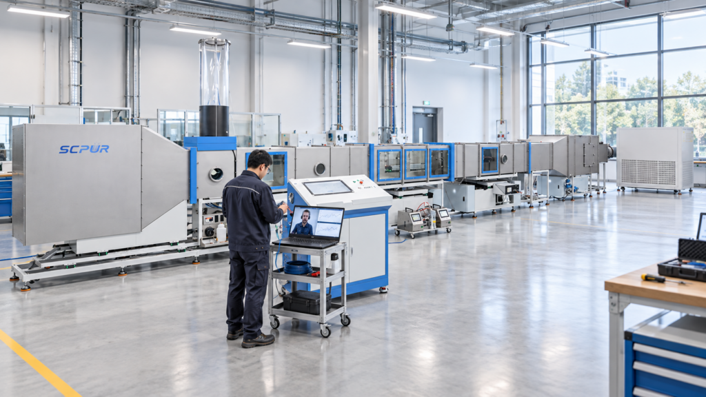
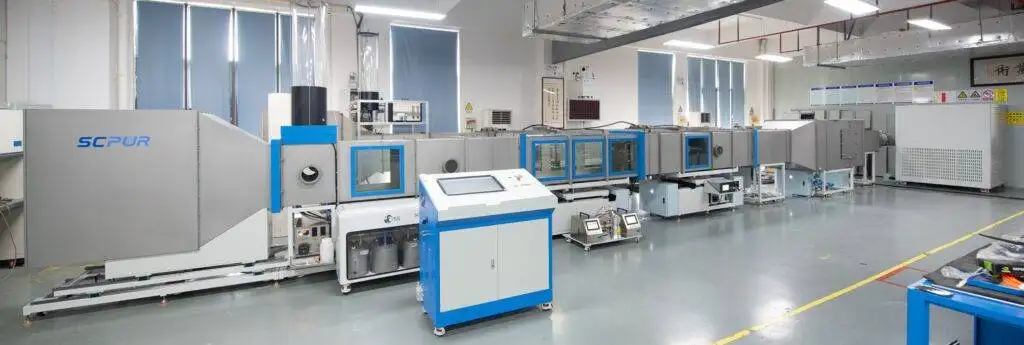
SCPUR परीक्षण प्रणालियाँ परिभाषित वायुप्रवाह के आसपास कॉन्फ़िगर की गई हैं, कण आकार, एकाग्रता, और फ़िल्टर-आकार श्रेणियाँ. फ़िल्टर मीडिया या छोटे फ़िल्टर तत्वों के लिए, the SC-FT-1406D-Pro तेल के साथ नियंत्रित दक्षता और प्रतिरोध परीक्षण प्रदान करता है- या नमक-आधारित एरोसोल विन्यास.
कम वायुप्रवाह विसंगति के लिए, उपयोगी आउटपुट केवल पास/असफल मान नहीं है. यह एक दोहराने योग्य परीक्षण रिकॉर्ड है जो अलग-अलग वायु प्रवाह नियंत्रण में मदद करता है, एयरोसोल पीढ़ी, नमूना, रिसाव, और फ़िल्टर स्वयं.