

“HEPA filter leak test” is used for two different activities:
- testing an individual filter element at the manufacturer’s factory; et
- testing an installed filter, its gasket, housing, and surrounding installation in a cleanroom or air-handling system.
The two tests have different boundaries, procédures, and acceptance criteria. Confusing them can lead to the wrong equipment specification or an unsupported compliance claim.
1. Factory Scan Testing of a Filter Element
1. Factory Scan Testing of a Filter Element
Factory scan testing evaluates the local performance of a finished filter before it is installed. Under EN 1822 et ISO 29463, the test is linked to the filter’s MPPS performance and nominal airflow.
The purpose is to detect unacceptable local penetration caused by defects such as:
- pinholes or damage in the filter medium;
- discontinuities in the medium-to-frame sealant;
- defects around separators or pleat packs; et
- local construction damage introduced during production or handling.
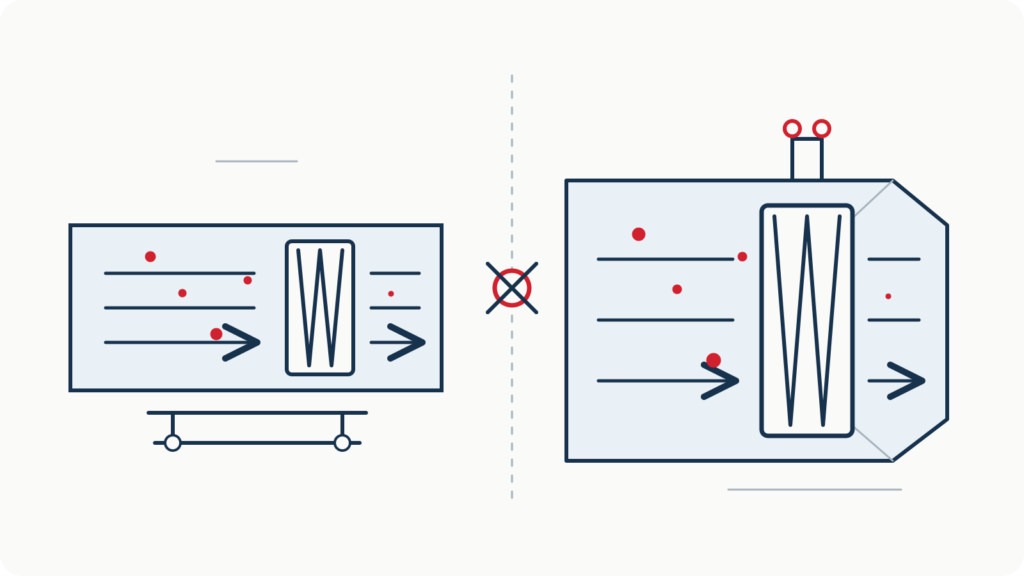
The boundary is the filter element itself. The building housing, ceiling grid, installation gasket compression, and bypass around an installed frame are not part of this factory test.
2. Installed-System Integrity Testing
2. Installed-System Integrity Testing
After a filter is installed, an integrity test can evaluate the complete installed filter system. Depending on the specified method, this can include:
- the filter medium;
- the filter frame;
- the gasket or gel seal;
- the housing and mounting interface; et
- bypass leakage around the installation.
Installed-system testing is commonly associated with cleanroom qualification methods such as ISO 14644-3 and with project-specific pharmaceutical or facility procedures. It does not reclassify the filter under EN 1822 ou ISO 29463.
A filter can pass its factory scan test and later fail an installed-system test because of installation damage, inadequate gasket compression, housing leakage, or bypass. Inversement, an installed test does not replace the manufacturer’s filter-element classification test.
3. How a Factory Particle-Counting Scan Test Works
3. How a Factory Particle-Counting Scan Test Works
A typical automatic scan sequence includes the following stages.
Establish the Test Condition
Establish the Test Condition
The filter is installed and sealed in the test rig, and the nominal airflow is established. Pressure drop and airflow are recorded under controlled conditions.
Generate and Condition the Challenge Aerosol
Generate and Condition the Challenge Aerosol
A stable aerosol is introduced upstream and mixed to achieve an appropriate, uniform challenge concentration. For standards-based classification, the test particle size must correspond to the applicable MPPS procedure.
Measure the Upstream Reference Concentration
Measure the Upstream Reference Concentration
The upstream concentration provides the reference for calculating penetration. If it drifts, downstream counts cannot be interpreted correctly, so the system must monitor concentration stability and apply the specified sampling sequence.
Scan the Complete Downstream Area
Scan the Complete Downstream Area
One or more probes move across the downstream filter surface and the relevant frame/sealant region. The scan path must cover the required area without gaps. The system records the probe position and downstream particle counts.
Calculate Local Penetration and Identify Abnormal Areas
Calculate Local Penetration and Identify Abnormal Areas
Local penetration is determined from upstream and downstream measurements. If a point or region exceeds the applicable limit, the system records its position for inspection, repair, and verification.
Determine Integral Efficiency Where Required
Determine Integral Efficiency Where Required
Local leak scanning and integral efficiency are different results. A complete standards-based evaluation can require both the local test and the overall filter-element efficiency test.
4. Acceptance Limits Are Class-Specific
4. Acceptance Limits Are Class-Specific
There is no universal rule that a HEPA filter leak must be “≤ 0.01%.” Under EN 1822-1:2019, le MPPS limits include:
| Filter class | Minimum integral efficiency | Maximum integral penetration | Maximum local penetration |
|---|---|---|---|
| H13 | 99.95% | 0.05% | 0.25% |
| H14 | 99.995% | 0.005% | 0.025% |
The values apply within the stated standards procedure and test conditions. Other classes, alternative methods, installed-system tests, and customer specifications can use different criteria.
Le 0.01% figure is therefore not a general H13/H14 local leak limit. In ISO 29463-1:2024, 0.01% is the maximum integral penetration for ISO 40 H, an intermediate ISO class without an exact EN 1822 class equivalent.
5. Why Scanning Speed Cannot Be Specified Alone
5. Why Scanning Speed Cannot Be Specified Alone
A product brochure may list the mechanical speed capability of a scanning axis, but a standards test cannot be defined by a single universal speed such as 10 cm/s.
The permissible scan speed depends on the complete measurement condition, y compris:
- probe inlet area and scan-track spacing;
- particle-counter sampling flow;
- upstream aerosol concentration;
- expected local penetration limit;
- detector response and transport delay;
- sampling interval and count statistics; et
- whether one or multiple probes are scanning simultaneously.
The software should determine or limit the test speed from the configured method. A faster axis can improve return and positioning time, but it must not reduce the probability of detecting a relevant local leak.
6. Probe Coverage and Positioning
6. Probe Coverage and Positioning
Complete coverage is as important as detector sensitivity. The scan plan should account for:
- probe width and effective inlet area;
- overlap or spacing between adjacent tracks;
- distance and orientation relative to the filter surface;
- edge, cadre, and sealant regions;
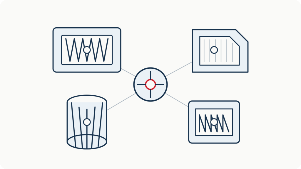
- pleat or V-bank geometry; et
- areas that require manual confirmation because they cannot be reached by the automatic probe.
For irregular filters, a combined automatic and manual procedure may be more reliable than claiming complete automatic coverage where the probe cannot physically reach.
7. Manual vs Automatic Factory Scanning
7. Manual vs Automatic Factory Scanning
Manual scanning can be useful for development work, confirmation, repair location, and unusual geometries. Its limitations are operator-dependent speed, probe distance, couverture, and data recording.
Automatic scanning provides:
- consistent probe movement and track spacing;
- repeatable test speed and sampling time;
- coordinated position and particle-count data;
- automatic leak mapping;
- traceable pass/fail logic; et
- repeat testing of repaired areas.
Automation does not remove the need to configure the correct standard, class, MPPS, airflow, aérosol, and detector. It makes a valid procedure more repeatable; it cannot make an invalid configuration compliant.
8. Equipment Required for an Automatic Factory Scan Test
8. Equipment Required for an Automatic Factory Scan Test
A complete system can include:
- controlled airflow and differential-pressure measurement;
- a filter fixture with reliable sealing;
- génération d'aérosols, mélange, and concentration control;
- upstream reference sampling;
- one or more downstream scanning probes;
- an optical particle counter or condensation particle counter suitable for the required class and particle range;
- a motion system with position feedback; et
- software for sequencing, count evaluation, leak mapping, reporting, and traceability.
The sensitivity needed for H13 is very different from that needed for U16 or U17. Detector selection and concentration control must be based on the lowest penetration that must be measured.
9. The Role of the SCPUR SC-L8023/U
9. The Role of the SCPUR SC-L8023/U
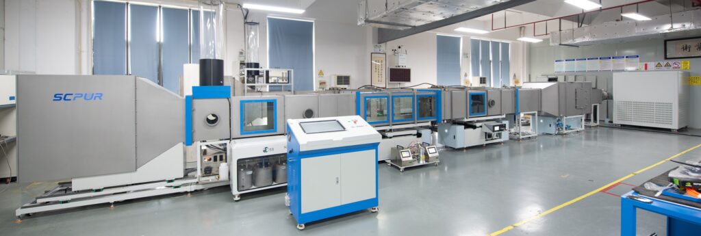
Le SC-L8023/U Automatic Scanning Test System is designed for factory testing of high-efficiency filter elements. Depending on the selected configuration, it can integrate controlled airflow, automatic scanning, mesure des particules, concentration monitoring, leak mapping, and integral performance verification.
System configuration is selected according to:
- filter class and applicable standard;
- filter dimensions and geometry;
- nominal airflow and pressure drop;
- required particle-size range and detector sensitivity;
- number of scanning probes;
- production throughput; et
- whether the customer needs internal QC or formal standards-based reporting.
10. Questions to Answer Before Selecting a Leak-Test System
10. Questions to Answer Before Selecting a Leak-Test System
- Is the filter being tested before installation or as part of an installed system?
- Which standard, edition, and filter class must be reported?
- Is MPPS determination already available for the filter medium?
- Is the test intended for internal production screening or formal classification?
- What filter sizes, shapes, airflows, and pressure drops must be covered?
- What local penetration must the detector measure reliably?
- Is automatic full-surface coverage possible for the filter geometry?
- Must the system support repair mapping and retesting?
Clear answers to these questions prevent factory classification, production screening, and installed-system integrity testing from being mixed together.
- Automatic Scanning Test System SC-L8023/U
- Salle blanche HEPA Filter Validation and Leak Testing Solutions
- EN 1822 contre ISO 29463: Classes, Tests and Key Differences
- BS EN 1822-1:2019 — Classification, performance testing and marking
- ISO 29463-1:2024 — Classification, performance, testing and marking
- ISO 29463-4:2011 — Test method for determining leakage of filter elements, scan method
- ISO 29463-5:2022 — Méthode d'essai pour les éléments filtrants
- OIN 14644-3:2019 — Cleanrooms and associated controlled environments, méthodes d'essai